Schematic Symbol Creation
Symbols and Assemblies
Summary
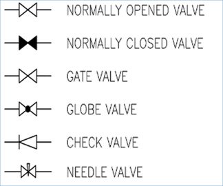
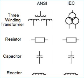
This TecSurge service delivers application reference data including 2D symbols for Intergraph’s schematics software, including SmartPlant Electrical, SmartPlant P&ID and SmartPlant Instrumentation.
In each case, TecSurge prepares and configures the graphic symbols and reference data required to generate graphical diagrams, reports and schematic outputs from the applications, including:

- P&ID: diagrams
- Electrical: single line diagrams
- Electrical: block diagrams
- Electrical: schematic diagrams
- Instrumentation: loop drawings
- Instrumentation: wiring reports
- Instrumentation: cable block diagrams
Differentiators
- Deep understanding of engineering design procedures and requirements, combined with hands-on practical software experience, minimize delivery schedule and cost
- Years of experience with previous and current versions of SmartPlant schematics applications, delivers rapid implementation and trouble free performance
Deliverables
Deliverables typically produced by this service are:
- For SmartPlant P&ID
- 2D graphic symbols
- Updated Line styles
- Updated Symbol Rules
- Updated Select Lists
- Drawing templates
- For SmartPlant Electrical
- 2D graphic symbols for single line, block and schematic diagrams
- Updated Line styles
- Updated Select lists
- Drawing templates
- For SmartPlant Instrumentation
- 2D graphic symbols for loop and wiring reports, and cable block diagrams
- Enhanced Report drawing templates
Work Process
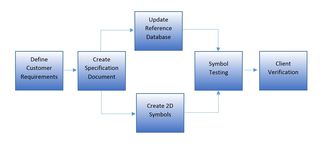
TecSurge manages the execution of Schematic Symbol Creation as a professional services project, involving a dedicated project manager and our expert services team. Typically, the project schedule will be developed based upon milestones aligned with our client’s project priorities.
These priorities and deliverables associated with each of the project milestones are agreed with the client during the project kick-off meeting, after which the detailed execution commences.
Requirements are finalized by creating specification documents for the project with all the technical details such as data mapping and line symbology. These specification documents are issued to the customer for approval prior to the commencement of development work.
As each milestone is reached, a set of quality checked, ready for use symbols and reference data is delivered, along with a project status report. Drawing and report configuration and reference data is typically provided after all symbols and assemblies have been accepted.
Quality Assurance
Prior to the issue of deliverables, every symbol developed is tested on an environment utilising the updated reference library. Upon successful completion, the handover package is sent for customer verification.
During the customer verification period, the client confirms their acceptance of the customised symbols and provides comments or feedback regarding the delivered package. Any issues raised during this stage will be resolved until final handover is completed.
Getting Started
Design companies use a combination of industry, corporate and project standard methods of representing entities in schematic drawings. Because of this, each new project may require the preparation of a new library of symbols and drawing templates appropriate to the circumstances and standards applicable.
In order to start the configuration, our clients usually provide a symbol legend sheet to be used in the project. CAD data source is the recommended format for this, so that the symbol scale will be the precise match the operational environment. The client also needs to provide details on additional data input fields which may be required for their workflow.
Mapping of data to fields follow the product standard implementation methodology. Additional company-specific fields required are documented as part of the handover documentation.
If Schematic Symbol Creation is a service that you need, contact us today for quotation.

